The RoboCNC Optimum BF20L mill that we have been converting to CNC needs a nice controller.
Till now we where only used to drive CNC using the parallel port and Mach3.
For the RoboCNC Optimum BF20L we wanted something new like USB.
We do not sell controller like this but we encourage you to build your own using our information (at your own risk!).
We provide all info for free, and the same applies to all drawings.
When you use any of this a link back or some RoboCNC credits are more then welcome.
First of all i needed a new controller enclosure, these universal enclosures aren’t cheap but well…
I found a suiteble one at https://www.rs-online.com/ part number :818-637
The external size is approx l=367mm w=300mm h=134mm.

In the video below you can see how we replaced the front and back panel for a custom one.
We engraved the anodized aluminum and oxidized the engravings to make it black.
So lets have a look inside this magic box…
In the schematic you see below we see the ‘mains power in‘ on the left.
This is where the 220V enters the CNC controller, 2 10amp fuses and an EMC filter are included.
We will use USB connection for the data, thats why we use this EMC filter to prevent electromagnetic noise problems.
The main power goes through a switch in the front of the controller (coordinate 08B).
When this switch makes contact the 12V power supply is set to work.
The power supply lights the ledring in the switch, is used for multiple sensors, and it powers SSR No. 1.
SSR (Solid State Relay) No. 1switches the power on for the 68V power supply. (yes the picture 78V is wrong).
The 68V 7Amp Leadshine SPS705 power supply will be used to power the stepper-motors.
The reason I have switched this through SSR is to keep the switching current nice and low.
On the Right we see SSR No 2., this one is used to switch the mains-power-out to the Neutrik NAC2MPB.
This output can be used to power a spindle or a pump for example. (and will be controlled using the computer).

The next page on our RoboCNC USB Controller speaks for it self.
On the left the 68V DC travels directly to the 4 stepper-drives.
The Stepper-drive output is connected to the heavy duty Neutrik NC5FD-LX and the NC5MXX connectors.

The stepperdrives we used in this cnc controller are Leadshine Digital DM856
These are digital drives rated up to 80Vdc and 5,6Amps.. See my digital test video below:
In the drawing below we see the actual CNC controlling brain.
This board is called the USBCNC cpu5a 4-axis and comes with it’s owns software.
We are fairly new to this hard, and software, so for full info checkout eddingcnc.com
The db9 connector top left is directly connected to the front panel for use of a pendant.
The mini USB is directly connected to the USB-B-type connector in the back panel for computer communication.
The DB25 is connected to a breakout-board with screw terminals to make connections more easy.
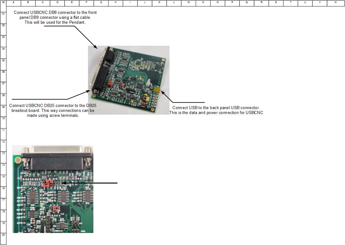
The 25 pin D-sub connector has be lead to a breakout-board.
In the schematic below you can see the pin-out we have used, and how we wired it all.
We gave the wires not only colors and a name, but the coordinates are given of where we connect them.
If you have any questions upon this matter please use the comments form below.
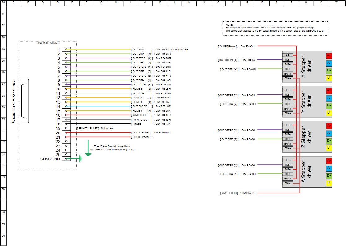
A lot of the DB25 outputs are wired to the stepper drive as seen above, but not all of them.
Some are used to drive CNC auxiliary, and of course the sensors.
For sensor connecting I used 5 pin DIN connectors, affordable and very good quality.
There are four connectors for home-switches X, Y, Z and A.
I will use the first three directly on the mill, and I guess the A will be used for an indexer later.
Shielded inductive NPN switches are used for this purpose, and are wired as shown below.
An E-stop is used as a “Normally Closed” contact wired to the back panel.
Using an NC contact you make sure that the machine stops, even if the cable breaks.
The next input is the Probe. I wired this to the back panel and the front panel (for ease of use).
This probe input will be used for tool-length setup, and digitizing purpose.
The VFD connector will be used to drive the frequency converter.
This will start, stop and control the speed of the main spindle.
More on this when we mount a 3 fase spindle motor.
Three outputs left that could start pumps or something like that.
For now I have called these FLOOD for flood-coolant, MIST for mist-coolant and
AUX for an auxiliary output yet to find its purpose.
The last two are not yet in use in my setup, but may well be in the near future.

The drawings as seen above are provided in PDF for free to use at your disposal.
Be advised that using this is at your own risk, we will not take any responsibility.
When you decide to use our information a link back, or something like that would be the least you could do.
The PDF document version 2 [April 2014]
Have a look at the quick overview video of this controller:
 © 2012-2024 RoboCNC.nl | RoboCNC.be | RoboCNC.eu - All Rights Reserved.
I was quite amazed to… ImpulseCNC told me if i would test them i would go for the DM. But I’m not convinced before i see for my self 🙂
I was quite amazed to… ImpulseCNC told me if i would test them i would go for the DM. But I’m not convinced before i see for my self 🙂
???????!
???????!
???? ??????. ??? ????? ??????????? ????????? ??????
heey die moet ik ook hebben op de morbivlerki haha…alleen dan de 230V versie.. echt verbluffend
Ik was ook enorm verrast…. De 230V heb ik niet getest… Sterker nog ik wil nog meer testen doen, maar heb wat tijd te kort 🙂
Ik was ook enorm verrast…. De 230V heb ik niet getest… Sterker nog ik wil nog meer testen doen, maar heb wat tijd te kort 🙂
All I can say is WOW!!! Thank you RoboCNC. This is a very informative video. I learned a lot.
Thank you Mike ! Glad you liked it !
Thank you Mike ! Glad you liked it !
Thanks for informative clip
Your welcome 😉
Your welcome 😉
both drivers can get the same RPM of the steppers or there is a winner?
There was no winner in speed, although i only tested without any load. At the high RPM’s the normal analog drive and digital one are pretty much the same.
There was no winner in speed, although i only tested without any load. At the high RPM’s the normal analog drive and digital one are pretty much the same.
Thanks
Very nice work 🙂
Thanks Oddmar !
Thanks Oddmar !
Wow – what a nice technique – I oftened wondered how I could darken or make anodized aluminum engraving POP!
Well than now you know 🙂 I’m glad to hear someone benefits from the information i post. Thanks Vicki !
Well than now you know 🙂 I’m glad to hear someone benefits from the information i post. Thanks Vicki !
Cool! I do like your projects. Even if you don’t use anodised alu, the top surface can be ‘lightened’ back with a fine sanding block after it got dried.
Hi h4z4rd42, Thanks for the nice comment… And that’s a great tip indeed… That way you could even polish the surface.. 🙂
Hi h4z4rd42, Thanks for the nice comment… And that’s a great tip indeed… That way you could even polish the surface.. 🙂
Very good job. Thanks for the info. 🙂
Your welcome…. 😉
Your welcome…. 😉
Very professional job!!! Robo, what do you think about Leadshine controllers? I know, that this chinese manufacturer is leader in built quality of chinese drivers…But, can you compare Leadshine quality and american Gecko drivers?? If i choose digital stepper driver from Leadshine, i get same speeds and accelerations as Geckodrive G540…? Or Gecko stepper drivers are still “state of the art”..?
Hi… Thanks for your comment. Its a bit early for me to do a full review on the drives. I have another video about these drives on my YT channel. They seem to be great against resonance (the digital ones). I have no experience in Geckodrive, and can not compare them therefor. Dont forget to check my other video with some tests.
Hi… Thanks for your comment. Its a bit early for me to do a full review on the drives. I have another video about these drives on my YT channel. They seem to be great against resonance (the digital ones). I have no experience in Geckodrive, and can not compare them therefor. Dont forget to check my other video with some tests.
now I have to find this or it’s equiv in the US Thanks for all the videos they are great!
Wat nou weer..This is awesome :P!!had ik nog niet gezien!
Leuk spul he…. 😉
Leuk spul he…. 😉
Did you test to see if microphone placement was an issue? On my phone the mic is right at the top left, it would be much closer to the louder motor than the quieter motor. Thanks for the video!
Hi FilterYT, Im not sure what side the mic is on…, so that may be true indeed. But than again using the phone is not an exact science, but just to give a general idea. You can also listen to the sound of the camera to hear the difference. (The video sound is not from the iphone but the camcorder.. ) Thanks for thinking along FilterYT.. Stay tuned..
Hi FilterYT, Im not sure what side the mic is on…, so that may be true indeed. But than again using the phone is not an exact science, but just to give a general idea. You can also listen to the sound of the camera to hear the difference. (The video sound is not from the iphone but the camcorder.. ) Thanks for thinking along FilterYT.. Stay tuned..
Good job What tool you used for engraving?
An Engraving bit 🙂 (30 degree wit a 0,1 tip i think)
An Engraving bit 🙂 (30 degree wit a 0,1 tip i think)
echt super mooi !!!! altijd een genot naar je filmpjes te kijken
thank you for you video. i bought digital stepper driver . during initial testing the motor was so quiet i thought driver got problem after seeing the shaft i could conform stepper motor was rotating. truly value for money .
Uploaded a video to YouTube about the new USB CNC Controller we put together for the RoboCNC Optimum BF20L mill..Full info on this CNC Controller will be posted later this week.RoboCNC BF20L 007 : RoboCNC USB CNC Controller overview
Uploaded a video to YouTube about the new USB CNC Controller we put together for the RoboCNC Optimum BF20L mill..Full info on this CNC Controller will be posted later this week.RoboCNC BF20L 007 : RoboCNC USB CNC Controller overview
Ik zie dat je de bestelde componenten erg netjes hebt ingebouwd!Goed werk!
You sure did squeeze that gear into a small box, very tidy the short pieces of shielded cable are a nice touch on the stepper driver outputs but not sure if you really need it on such a short run keeps it tidy thanks for the look. 🙂
Very professional work, nice case and best chinese manufacturer inside!! Your hands is grow up from the right place, Robo))
Okee dan!!! :-))
Hi-tech stuff!
Did you ever try testing the driver and motor after tuning them with the software? I am very curious to see if the performance is any better!
Hello RoboCNC,
First of all, your CNC controller looks amazing. Very professional job.
I’m also converting my BF20L to CNC and I’m currently building a similair controller (but with a C10S BOB).
In your last video on the page you show us the insides of your controller. I see that for both power supplies the DC ground terminals are bridged to the AC earth terminals. Why is that? Is that to cancel out any noise buildup in the system?
Btw, I have very basic understanding of electrical circuits. I always thought that not floating the ground could potentially be hazardous.
Cheers JQ
Hi Jq,
Thanks for your comment and compliments.
This is the third controller I have build and indeed i tend to keep everything grounded to the same level.
Also all the DC negatives are grounded, this way all voltages are referenced from the same 0 / ground, so the positive lead is really 12V higher than ground, not just 12V higher then the – / 0 .
Systems like stepper controllers are indeed very likely to create noise and magnetic interference, and boards like the USB controller can become faulty with interference like this.
I think the ground problem you are referring to would be a “ground loop”, this would be the case if you for example also connect the cable shield to ground at the stepper side.
I’m not a real expert in this matter but I do know that this works great, and i have not found any issues..
Cheers.. Marcel
Why do you use a “unregulated” power supply and is not regulated? I don’t understant the diference…
If you do not now the difference, why doubt the setup? 🙂
Anyway, I’m not trying to built a lab-power supply…
I’m using power to drive the CNC components inside the cabinet and the motors and sensors..
The power supply (made by the steppermotor, and stepper drive builder) is more than sufficient in doing everything I ask from it and it is compact.
If I misunderstand your question please let me know…