The RoboCNC Optimum BF20L mill that we have been converting to CNC needs a nice controller.
Till now we where only used to drive CNC using the parallel port and Mach3.
For the RoboCNC Optimum BF20L we wanted something new like USB.
We do not sell controller like this but we encourage you to build your own using our information (at your own risk!).
We provide all info for free, and the same applies to all drawings.
When you use any of this a link back or some RoboCNC credits are more then welcome.
First of all i needed a new controller enclosure, these universal enclosures aren’t cheap but well…
I found a suiteble one at https://www.rs-online.com/ part number :818-637
The external size is approx l=367mm w=300mm h=134mm.

In the video below you can see how we replaced the front and back panel for a custom one.
We engraved the anodized aluminum and oxidized the engravings to make it black.
[youtube]httpss://www.youtube.com/watch?v=VUj5E06HYyg[/youtube]
So lets have a look inside this magic box…
In the schematic you see below we see the ‘mains power in‘ on the left.
This is where the 220V enters the CNC controller, 2 10amp fuses and an EMC filter are included.
We will use USB connection for the data, thats why we use this EMC filter to prevent electromagnetic noise problems.
The main power goes through a switch in the front of the controller (coordinate 08B).
When this switch makes contact the 12V power supply is set to work.
The power supply lights the ledring in the switch, is used for multiple sensors, and it powers SSR No. 1.
SSR (Solid State Relay) No. 1switches the power on for the 68V power supply. (yes the picture 78V is wrong).
The 68V 7Amp Leadshine SPS705 power supply will be used to power the stepper-motors.
The reason I have switched this through SSR is to keep the switching current nice and low.
On the Right we see SSR No 2., this one is used to switch the mains-power-out to the Neutrik NAC2MPB.
This output can be used to power a spindle or a pump for example. (and will be controlled using the computer).

The next page on our RoboCNC USB Controller speaks for it self.
On the left the 68V DC travels directly to the 4 stepper-drives.
The Stepper-drive output is connected to the heavy duty Neutrik NC5FD-LX and the NC5MXX connectors.

The stepperdrives we used in this cnc controller are Leadshine Digital DM856
These are digital drives rated up to 80Vdc and 5,6Amps.. See my digital test video below:
[youtube]httpss://www.youtube.com/watch?v=iryj1bJlAd4[/youtube]
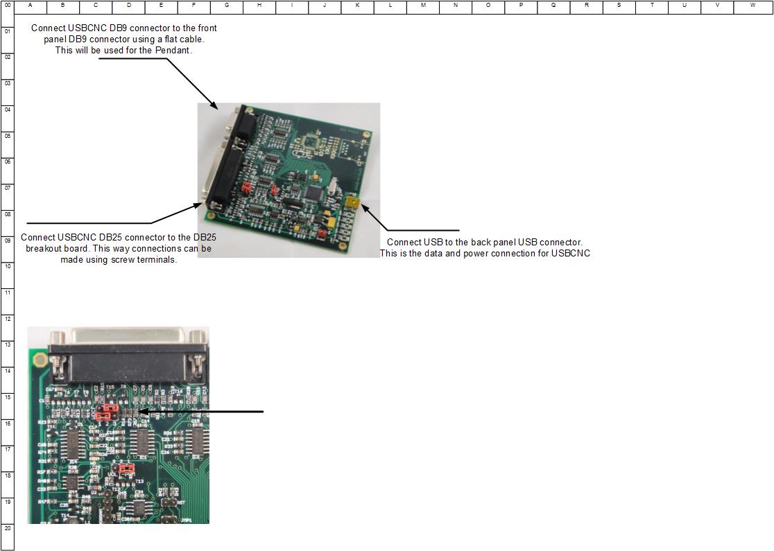
In the drawing below we see the actual CNC controlling brain.
This board is called the USBCNC cpu5a 4-axis and comes with it’s owns software.
We are fairly new to this hard, and software, so for full info checkout eddingcnc.com
The db9 connector top left is directly connected to the front panel for use of a pendant.
The mini USB is directly connected to the USB-B-type connector in the back panel for computer communication.
The DB25 is connected to a breakout-board with screw terminals to make connections more easy.
The 25 pin D-sub connector has be lead to a breakout-board.
In the schematic below you can see the pin-out we have used, and how we wired it all.
We gave the wires not only colors and a name, but the coordinates are given of where we connect them.
If you have any questions upon this matter please use the comments form below.
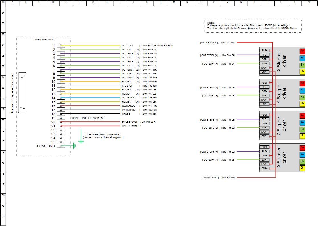
A lot of the DB25 outputs are wired to the stepper drive as seen above, but not all of them.
Some are used to drive CNC auxiliary, and of course the sensors.
For sensor connecting I used 5 pin DIN connectors, affordable and very good quality.
There are four connectors for home-switches X, Y, Z and A.
I will use the first three directly on the mill, and I guess the A will be used for an indexer later.
Shielded inductive NPN switches are used for this purpose, and are wired as shown below.
An E-stop is used as a “Normally Closed” contact wired to the back panel.
Using an NC contact you make sure that the machine stops, even if the cable breaks.
The next input is the Probe. I wired this to the back panel and the front panel (for ease of use).
This probe input will be used for tool-length setup, and digitizing purpose.
The VFD connector will be used to drive the frequency converter.
This will start, stop and control the speed of the main spindle.
More on this when we mount a 3 fase spindle motor.
Three outputs left that could start pumps or something like that.
For now I have called these FLOOD for flood-coolant, MIST for mist-coolant and
AUX for an auxiliary output yet to find its purpose.
The last two are not yet in use in my setup, but may well be in the near future.

The drawings as seen above are provided in PDF for free to use at your disposal.
Be advised that using this is at your own risk, we will not take any responsibility.
When you decide to use our information a link back, or something like that would be the least you could do.
The PDF document version 2 [April 2014]
Have a look at the quick overview video of this controller:
[youtube]httpss://www.youtube.com/watch?v=cU1jFrIMisg[/youtube]