Last but not least the Optimum BF20L X axis conversion to CNC.
The X axis is the one that travels from left to right.. “The table”
First of all i mention this again:
Using the provided drawings and information is at your own risk.
I provide all this information for free so some credits would be great if you use them.
Any Forum, social media or YouTube refer is much appreciated.
The standard table of the BF20L is made for use of the TR / Acme thread.
The table ends are also not machined to use the new bearings either.
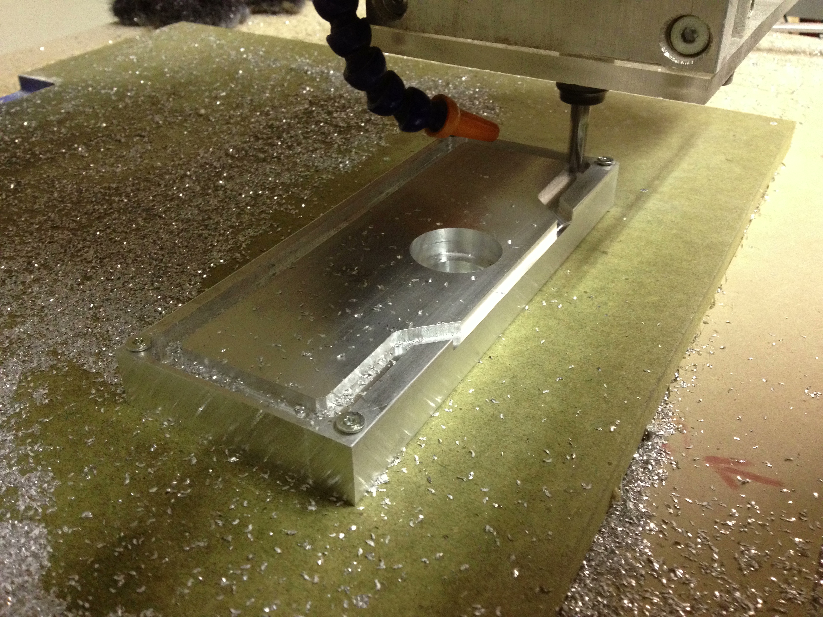
Conclusion is we need to make these our self’s.
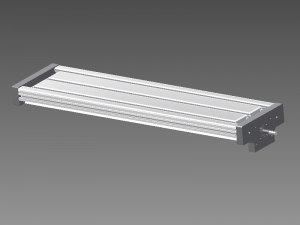
Making these out of aluminum 6061T6 using the following drawings:

Download these drawings : X Axis
On the left side (X- or X0) we are only going to support the lead-screw for radial forces.
I will call this the loose bearing side, as the leadscrew can freely slide in and out of this bearing.
It is important to do so on one side because the shaft/screw can expand if it gets warmer.
If it could not expand in length it would start to bend, and wobble.
The X+ side we will use a double row angular contact bearing.
This one will support the radial forces, but will be used as a thrust bearing also.
The X+ side also has the bolt pattern to fit the DamenCNC Nema34 stepper mounting plates.
Below we can see the table sides / bearings mounted on the table / machining bed.
The 4 holes around the bearing are tapped for bolts to secure the bearings in place
Used bearings:
One 3201/5201ZZ 12x32x15.9 (Double row angular contact bearing)
One 6201ZZ 12x32x10mm (Groove Ball Bearing)

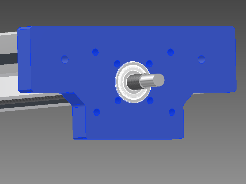


The leadscrew used is again RM1605 (found on Ebay : Linearmotionbearings2008)
I will now provide a drawing for all three leadscrews in ones.
When you order these make sure you buy 2 locknuts per screw.
It’s always smart to purchase some extra balls and nut replacement tubes.

Drawings : Ballscrew
Note: a small mistake is found in the pdf file. The thread should be 20mm (as in the jpeg)
The lock nuts as described above have small lock screws to secure them on the thread.
Besides the fact i do not trust this way of securing the nut, it can also ruin the thread on the shaft.
Therefor i do recommend to order two per shaft, and lock them like in the image below.
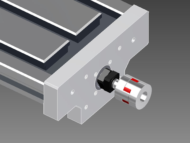
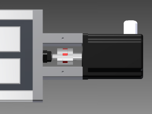
The Nema 34 stepper mounts I use are a very rigid way to place the big steppers.
Of course you can also make something yourself to reduce the cost, but do not use 4 standoffs.
I know from personal experience that this will give you torsion trouble, i see this around very often.
Order: Two Nema 34 Stepper Mounts Nema34Mount
On the right we see the Nema 34 4,5Nm IP54 (water tight) stepper motor.
Most conversions are done with way smaller steppers, and most are driven by belt.
A machine that is used for milling metals, well i do not think belts are appropriate.
Yes these motors are more expensive, but come one think about it.
One Nema 34 4.0Nm Stepper motor: DCNC-IP54-4.0NM
One Zero Backlash Shaft Coupler DCNC-D32-L32
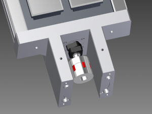
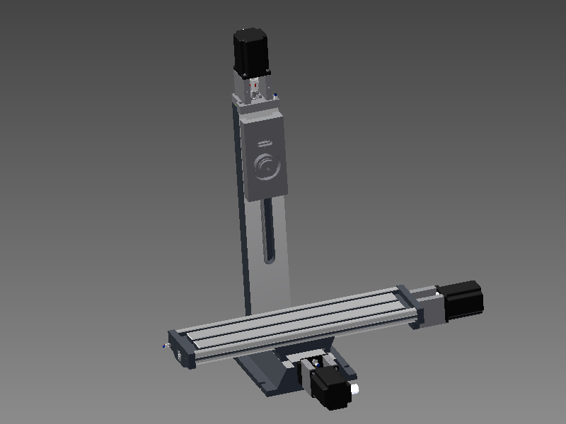
If we look at the three images below we see how all this has to come together.
The table / bed lays down on the saddle, with an adjusted gib (I will not do a tutorial on that).
And the ball-nut falls in to a square hole that was already in the saddle to begin with.
I know this hole is not present in all machines, but in mine it was, so otherwise you will have to machine it.
In the center image you can see that there is not enough space for the complete ball-nut.
So that needs to be modified to.


I have place the ball nut in the lathe to turn one side down as much as I could.
And i have removed the high spots (and paint) from the bottom of the machine bed.
Together this makes enough clearance for the lead-screw and its nut.


Follow up on Facebook to sneak preview the movement !
 © 2012-2024 RoboCNC.nl | RoboCNC.be | RoboCNC.eu - All Rights Reserved.
Sorry had to repost due to audio claims
Sorry had to repost due to audio claims
Sorry had to repost due to audio claims
As always, excellent job!
Thanks 😉 !
Thanks 😉 !
Thanks 😉 !
Dude, you rock, thanks for making the plans of the conversion of the BF20L to CNC available for free.
Thank you, thank you, thank you.
Thank you for the great comment David !
My BF20L was delivered today,ordered the ball screws from your contact at a great price, can not wait to get started on the cnc conversion. Once again thank you for making the plans and movies available, you have me all exited about the build. I am a computer programmer but the cnc stuff has always fascinated me, hope this new adventure can change my outlook on life, very bored with the coding. Will keep you posted on the build.
Congrats on the BF20 David… !
Again it’s great to hear you enjoy and benefit the information I share.
Good luck with the conversion, and have a great adventure machining your first parts !
Let’s keep the chips flying, and try to combine your programming skills by using them for machining scripts.
I will be posting a new video soon on the controller…
Marcel…
Hi,
Would you please explain why in your presentation the ball screw set for
X-axis and Z-axis have approximately the same length i.e. the X-axis is
755 mm long and the Z-axis is 750 mm long. After all we are talking about
the CNC machine OPTI BF 20L VARIO.
Regards,
Dragi,
Hi Dragi,
Thanks for your comment, and the sharp eye on the project ;).
The X axis for the BF20L is drawn exactly at the length needed for this conversion.
For the Z axis you are right, this spindle is longer then needed for this mill as it is right now.
The reason i have left this spindle at this length is that it fits in there at this length.
I tend to modify machines as i go along, and this way i could always modify travel on the Z-axis if i would need / want to.
For the price of the spindle it is smart to leave it like this, as the extra length does not effect the price that much.
The only down side could be the extra inertia of the spindle, but with this milling head being so heavy i can not think this will effect it very much.
So if you are sure you will not modify Z ever, you could indeed order a shorter Z lead-screw indeed.
Hope this answers your question Dragi.
Best regards,
Marcel
Altijd kijk ik met veel plezier naar deze step by step video’s van je. Je werk ziet er altijd tiptop uit !
Altijd kijk ik met veel plezier naar deze step by step video’s van je. Je werk ziet er altijd tiptop uit !
Altijd kijk ik met veel plezier naar deze step by step video’s van je. Je werk ziet er altijd tiptop uit !
Hello Marcel,
your work is really nice, your pages are well explained and your information is valuable and you give everything for free… thanks a lot.
– What is the electronic (boards and drivers) you will be using for the BF20?
– you didn’t let the possibility to move the axes manually (if not for a jog), a compromise or a wanted choice?
– will you keep the same spindle motor?
thanks again
adriano
Hi Adriano,
Thanks for your nice and positive feedback.
I will post full information ans drawings on the electronics soon, still have to find time to do so.
For now i can tell you i will drive all stepper with digital leadshine drivers, run with USBCNC.
Having hand-wheels to manually operate the machine manually is like cursing in a church 🙂
On a CNC machine hand wheels are just not welcome 🙂 (apart from the unnecessary inertia they bring to the axis.)
Of course we will use a jogpad / pendant for moving the axes.
For now i will use this spindle motor, although I have a 3 fase VFD motor ready, but that will be a modification for later in next year.
Thanks,
Marcel
Thank you for the informative series you have done on this project. Very helpfull. Now that you have run it for a while, how are your experiences with this setup? Any changes you would like to make to your design?
Hi Marcel,
Thanks for posting this useful information for the public.
I was just looking at the order drawing that you provided for download and looking at the drawing on your page and they are slightly different. On the x axis the thread for the m12 nut and the part where the bearing goes on are different lengths. Is the reason for this because of the M12 being close to the shoulder and we just add a washer to make up for the 5mm or is there some other reason ?
thanks,
Cliff.
Hi Cliff,
Thanks for your comment, nice to here someone can use the information I post.
Well now i see the difference indeed, and i have to dig back into my memories.
If I recall correctly you should order the one with 20mm Thread, or well I did.
The reason for this is the use of 2 lock nuts and that the bearing is only 15,9mm thick.
So do not use the pdf, but the jpeg in the rar file.
Thanks for pointing it out..
Marcel
Hi, Thanks again for the plans. I am going to change my mill too. Can you let me know how much the ball screw need to be cut? I missed that information. Anyway your videos are really instructive and help us, really appreciate your time and effort.
I am sorry, I meant ball nut (that parts was grinding off).
Hi Greg,
I just tried to cut of as much as possible without cutting into the cylindrical part, I did not measure it exact, sorry for that.
Good luck with the build !
Best regards,
Marcel
Thank you so much for your time and knowledge . I am a machinist of 20 years and found your site to be most informative on this subject . I am currently following your design and its proving to be easy and effective. Keep up the good work mate.
Thanks for the nice comment ! And good luck with the build !
Don’t forget to subscribe on our Youtube, as we will soon strat a new build..
Best regards,
Marcel
Hello Marcel, thank you for very informative posts. After a couple of years – is there something you would do substantially differently?
What is your experience in practice with your design?
And last question – on the Sides drawings, the coordinates of the holes centers are not defined (axis Y, X can be derived or is stated) – do you have by chance a version with the centers coords?
Thank you in advance, Jan
Hello Marcel,
in the meantime, I managed to fix/resolve last question in my previous post (using your dxf primarily).
I will still highly appreciate your view on other questions, let’s summarize as: “If you start now again, what would you do differently?”
Thank you again for a very inspirative and detailed descriptions.
After prod run I’ll be able to provide DesignSpark model files (rsdoc) of all parts to you (for eventual publishing on your site) or everyone else who could use these.
Thanky again, Jan
Hi Jan,
Well I do not use the machine that often so i’m not sure if my answer is very useful.
But I would not do anything different within the same budget.
I do think the original motor is really low quality so i would change that and go for a belt drive if i used it more often.
Best regards Marcel
Hello Marcel,
thank you for sharing your opinion. I already realized that the motor is the weakest part of the entire machine, so I’ll substitute the entire BF20 spindle head with a 2,2kW high speed spindle.
Thank you again!
Jan