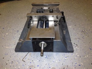
It’s time for the second axis to show some movement.
This time we will start working on the Y axis, just because the X axis is on top of Y.
Almost all info on the assembly can be seen in the YouTube movie.
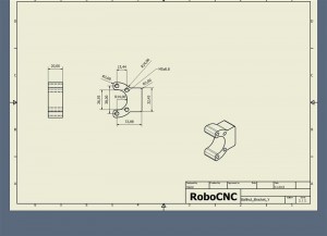
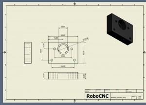
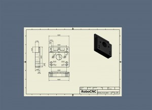
So just some quick drawings of the parts should be enough for this post.
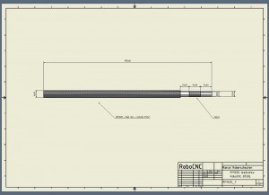
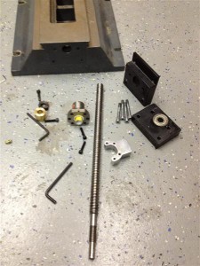
The first thing we need is the leadscrew, and for this axis I used the RM1605 (found on Ebay : Linearmotionbearings2008)
For the price its always smart to purchase some extra replacement balls and a second lock nut.
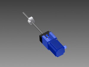
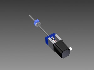
On the left we can see the drive parts for the Y-axis, where the blue parts are drawn in the right to order.
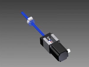
Drawing: Ballscrew_Y
The blue parts below are parts I can be bought at www.DamenCNC.com for example.
One Nema 34 4.0Nm Stepper motor: DCNC-IP54-4.0NM
One Zero Backlash Shaft Coupler DCNC-D32-L32
Two Nema 34 Stepper Mounts Nema34Mount
One 3201/5201ZZ 12x32x15.9 (Double row angular contact bearing)
One Inductive Switch Shielded 12NOC2A-S NPN
And a hand full of bolts… 😉
Now the last three parts that you will really have to make your self
1. The ball nut bracket that drives the saddle.
2. The housing for the angular contact bearing
3. The adapter plate that wil be used to fix the stepper mounts on (and the home sensor).
YouTube assembly video :
nema 34?? woot! is wel overkill ma torque genoeg :p maar echt wel mooie setup. welke sensors zijn dat btw ??
De reden voor deze motoren is dat ik per definitie slechts direct drive wil. Ik ben geen groot voorstander van een pully setup om het moment te verhogen. Bedankt in ieder geval 😉 !
That is one solid looking machine. Is this the retro fit of an existing mill or are you building this from scratch?
Ps.. Sensor info vind je op de website. Klik in de beschrijving even op de full info link.
Thanks buddy.. ! Yes this is the retrofit of the Optimum BF 20L Vario machine.
Just managed to find the Optimum website. You are going to have a great machine when you finish. Waiting for the next installment.
Its something really different indeed… It will make machining hard materials a lot easier.. As we speak the last axis is already done, still need to make the video and web page.. Will be updating soon. Thanks for watching !
thanks 🙂
Your project is very interesting. Good work!!! Are you ready with X-axis? Thanks, Zsolt from Hungary
Thank you Zsolt,
The X-axis is done indeed, but i did not yet have the time to post this.
Keep track on hour latest updates trough Facebook..
Thanks
Please, share the CAD drawings for X-axis. It is a very good project.
Thanks
Hi Zsolt,
You are right, i have to do so, man i am way to busy…
I will try to upload the new page as soon as possible.
In the mean time, if you need some information just contact me using the contact form.
Thanks..
I’m finding the Y movement to be a little restrictive. Some people are opening up the area where the nut moves, to allow more -Y movement. Next time I tear my machine down, I’m going to probably do this. Also, do you have a link for where you got the proximity sensors from? Are you finding they have good repeatability?
Not yet sure how the new YouTube comments work, but here we go.I hope you receive your reply DrFiero :)I can imagine the restriction you feel in the Y axis. But when going even further the saddle is hanging over the edge of the base quite a bit. I wonder if this will not give any problems. For the proximity sensors please follow the [Full info link].I have not yet done full testing on them, but they seem to do quite good.
This buildblog with drawings has been a great help, thank you for that.
It may be a stupid question but just wondering about the non motor side of the Y-aksis. No need for a radial bearing? I realize the dovetail will conteract the forces, but is there no danger the oposite end will move and contact the walls of the hole?
Sram
Hi Sram,
Thanks for your comment, and question.
The radial bearing in the end of the Y axis is not needed as it is not that long (like the X axis for example).
The same applies toe the Z axis (loose at the bottom) and Its seen a lot in router Z axes as well.
To work this way you do have to use a combination of a radial and an thrust bearing on one side, or angular contact bearings.
Why do i work like this? Well it has 2 advantages.
1: It’s more easy, I do not have to design or machine something for the other side of the shaft.
2: It’s more forgiving for slight aligning mistakes… Yes we do try to align perfectly but well.. we try 🙂
I hope this second reason makes sense when you think about it, if not please say to, then I will try to be more precise.
Best Regards,
Marcel
Hi there,
shouldn’t the machining of the screw be 15mm instead of 20mm where it is supported by the bearing (15.9mm thick)? otherwise you have the screw with lot of play and you must put some washers.
For the X and Z axes you have 15mm and I would do the same here. Why this?
thanks
Hi there Adriano,
Thanks for watching and thinking with me…
Please make sure to check the video, and zoom in at 3:00 min. till 4:00 to see why i did this.
You could use your methode, but then the lock-nut would have to be tightened within the second space/adapter plate.
You could tighten it befor placing the second spacer, but then you could never adjust it (or not easy).
Leaving the second adapter plate away is not an option to, because then the bearing would not be supported..
So indeed I choose to use a bushing (washers would do, although i’m not a big fan of using multiple on top of each other).
Hope this is helpfull, and we agree, but if you have better ideas please share them with the world here..
Thanks !
Best Regards, Marcel aka Robo
Hi there I almost completed all the parts for the cnc conversion and now I wonder how you join the ballnut braket to the y saddle. There are no holes for screws and you just insert it in the hole already present. But this is not a tight fit I suppose so how do you remove possible backlash? With calibrated gauges or what? Thanks.
Just trying to have all sorted out before dismounting and proceed to the conversion. Please keep on posting your ideas. Thanks
Hi Adriano,
The ballnut bracket is indeed fit in the hole thats present in the saddle.
But in my case there are 2 screws to tighten the bracket (as it is indeed not a tight fit).
If you look at the sadle from the back side (below the rubber splash guard) there are 2 hex bolts inserted to tighten the bracket.
These where used in the original setup also by the way…
Watch the video closely from about 6:50 minutes, you can see what i mean..
grtzz Marcel..
Thanks. I understand now. Is it the same also for the x axis isn’t it? I thought the two holes in the ballnut were used with the two screws of the saddle but these are roughly 22mm apart while the holes in the ballnut are at ~27mm. Thanks indeed for your inputs.
Hi Marcel
Firstly thanks for your build log it has been a great help already.
I have a Luxcut DM20VS which is essentially a BF20. It does not have the large pocket in the Y slide for the X ballnut but that is not a big problem.
When I opened the IDW files for the X and Y Inventor wanted the IPT files. Is it possible to get all the files from you?
Another question is in regards to the Double row annular contact bearing. A friend of mine says there is no way to adjust the backlash if you only have one. Do you find the shaft backlash acceptable? Is there any benefit in using thrust bearing rather than the DRAC bearings?
Thanks again – very helpful
Bruce
Wellington
New Zealand
Hi Bruce,
It’s great the files and build log are helping you.
If you need a ‘specific’ file you can always email me, but I’m not willing to send out the complete assembly of the mill.
I will also not send ‘The X and Y files’ so if you need something be really specific please.
I do not seem to understand your friend, and his concern about the bearing…
Using DRAC is much more preferred than using a thrust bearing for what i know.
The backlash comes from the spindle and it’s ball-nut, controlling backlash is mostly using you wallet when buying the spindle.
The bearing has no backlash as far as I know… When using a single row you would only need to take care when mounting (the are directional).
If you do want to use thrustbearings you would have to alter the design. It would take a thrustbearing AND a radial bearing to complete the job of a DRAC.
Good luck with the build Bruce, and show us when done !
Best regards,
Marcel – The Netherlands..
Hi Marcel
Thanks for your comments especially about the DRAC bearing.
I will look at what Inventor is asking for in the IDW file and send through a request. I want to be able to produce the file so that my friend (the same one who doubts the DRAC bearings) can manufacture them on his CNC SX3.
Really all I am after is the X & Y parts that need to be made not the whole mill.
Regards
Bruce
You are a lucky guy Bruce…
Your friend machines it.
I made the drawings, and all you have to do is find out what drawing you are going to ask my by email.. 😉