Now the CNC Controller is completed its time to setup Mach3.

Before I get a lot of questions “Yes I do use a different screen set”.
It’s called Mach3 Blue Screenset for Mills and can be found on Machsupport.

Before we go any further, I will not take any responsibility for whatever may go wrong.
For full info in setting up Mach3 i suggest you read the Mach3 manual and setup guide !

The first thing is to set the native units to mm or inch.
ConfigSelect Native Units

Now let’s setup the ports and pins…
Startup Mach3 and go to : ConfigPorts and Pins
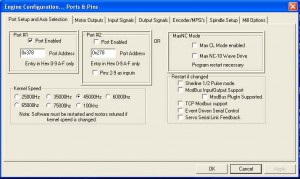
In the first tab ‘Ports Setup an Axis Selection’ you can select the port number and kernel speed.
This should be your DB25 port number and for kernel speed check the manual.
The Kernel Speed depends on the computer, the higher the pulse rate the faster the motors can turn.

Mach3_Setup_01

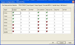
The second tab is for the Motor Outputs…

First Enable the axis you want to use, in my case its X,Y,Z and A.
Next are the PIN numbers on the BOB (Breakout Board).
These pin numbers are the pin numbers of the parallel port and the BOB for DIRection  and STEP = PLS .
In my last post with the drawings you can see the way these numbers are linked.
The PORT numbers should all stay on 1 if you work with 1 DB25 port.

Then the DIR and STEP should all be low active.
Remember that the Step and Dir signals where tied to the -DIR and -PLS of the drivers.

Mach3 Motor Outputs

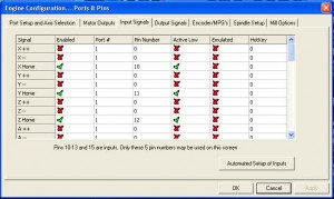
And now for the Input signals…

In the previous post I mentioned that you can use limit switches and home switches.
Well I only use 3 home switches, and use the software to apply ‘soft-limits’.
For Home X,Y and Z I used the pins 10, 11 and 12 on the BOB.
The pull-up resisters in my schematic Pull the signal UP to 5V unless the switch is pressed.
The when the switch is active (home position) the signal is LOW, therefore Active Low.

I did not use a home switch for A, although I’m planning to make an index on there later on.

Mach3 Input signals tab

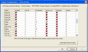
Now scroll down to the Probe, this is PIN number 13 on the BOB.
The probe is used for the Z-touch plate and for the digitizing probe.

The Estop is the only one that is not active low… Hmm why should that be?
The E-stop is a real piece of safety, not only for the machine but for myself.
Therefore the E-stop is a NC (normally closed ) contact, this is safer.
If the cable should break, or the connector or whatever the contact goes open and triggers.
So the estop makes the input low when inactive so is Active High.

Mach3_Setup_04

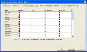
The next tab is the output signals, and in my case I only use 2.
I use 1 enable signal that enables all the stepper drivers when the software is ready.
And I use Output#1 to start or stop the spindle itself.

The ENAble signals where connected to PIN14,
and the Output to the SSR of the spindle was PIN1.

Mach3 Outputs

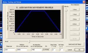
Now the Motor Tuning : Config Motor Tuning and setup.

On the right you can select the axis you want to tune, X in this picture.
Now we have to setup the steps per unit, where the unit is the mm or the inch.
If you use full-step the steps per revolution on the stepper motor is 200.
On the stepper driver I selected to use 8 microsteps so 8×200 = 1600 steps per revolution.
The reason for this is to let the motor run smooth and to have a very small resolution.
The pith of my X leadscrew is 5mm so 5mm/rev. how many steps would that be per unit?
1600 = 1rev = 5mm so 1600/5 =  320 steps per mm (1 step = 0,003125mm resolution)

Now the velocity (the maximum speed of the motor) can be set by number or the right slider.
Firstly set the Acceleration very low and  search what the maximum speed is of your axis.
In my case I can easily do the max slider position of 8500mm/min.
Now you can do the same with the acceleration.
Keep them both on the safe side, if you motor stall’s at 2500mm/min don’t put it on 2490 :).

Mach3 Motor Tuning

If you also use a rotational axis like me u have an A-axis to.
To set the steps per again check your micro steps (8)  : 8×200 = 1600 steps per motor revolution.
In my rotary axis I use a gear ratio of 1:6 so the motor must do 6 revs per chuck rev.
So 1 revolution of the part would be 1600×6= 9600 steps.
As this is a rotational axis 1 unit is not 1mm but 1degree therefore this needs to
be divided by 360degree’s (1rev) : 9600/360= 26.666666 steps per degree.

The pulse length depends on the speed of your electronics, I just leaf it on 2us per pulse

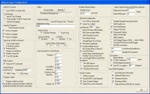
Now the general config, well just have a look at this picture for my settings.
If you have any questions feel free to ask, or check the manual.

Important is to set the A axis angular.
The CV control is important to understand.

Mach3 General config

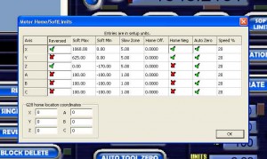
Now the config Homing and soft limits.

As i’m not using limit switches but soft limit I have to set this part up.
In the first column you can reverse the motor if it is going the wrong way.
The rotation of the motor depends on what side of the leadscrew you place it.
The soft max is the highest you want the axis to go from the home position (Soft Min).
The slow zone can be used to slow the machine down when it comes close to one of the limits.

The Z axis is done the other way around, top position is zero, end going down is negative.
This way you can zero on a part and machine negative into the part.
So X and Y would home to the negative position and the Z axis to the positive.

The auto zero is to set the machine coordinate system to zero when homing.
And the 20% speed is the % of max speed to use when homing the axis.

Mach3 homing and limits

Now save all your settings by Config Save Settings and your good to go.
Of course you can do way more settings, and you will do but for now you can start playing.

If you have any questions feel free to read the manual 🙂
Or just use the comment box beneath.

29 Comments

  1. TheRealAshiboy Says Beantwoorden

    [..YouTube..] heb je er veel plaats voor nodig?dat scherm op 1:30? is het niet makkelijker voor een touchscreen

  2. Marcelmx3 Says Beantwoorden

    [..YouTube..] @TheRealAshiboy Veel? plaats voor nodig?Ja een touchscreen zou erg mooi zijn inderdaad, maar helaas zijn er zo veel dure dingen mooi 🙂

  3. xumuk3 Says Beantwoorden

    [..YouTube..] Nice work!PWM makes miracles :)How large is voltage on power? part of controller?

  4. lezbriddon Says Beantwoorden

    [..YouTube..] /always look? forward to your vids.

  5. Marcelmx3 Says Beantwoorden

    [..YouTube..] @xumuk3 Indeed miracles, all 4 drivers are set to 4,2Amps and when i move 3 axis the current display stays below 3Amps.Thats what PWM does for me (although i don’t? know the refresh rate of the display)The breakoutboard gets 12V to the input, and 5V usb power for PC side.48V to the steppers…

  6. frozo12 Says Beantwoorden

    [..YouTube..] Really missed your work and your machine..!!?

  7. Marcelmx3 Says Beantwoorden

    [..YouTube..] @lezbriddon Thanks ! Well it was a bit quit on my YouTube channel, but there is more to? come 🙂

  8. Marcelmx3 Says Beantwoorden

    [..YouTube..] Thanks Frozo,Yeah sorry i had a busy time here… So? not a lot of YouTube video’s..But the machine is up and running again, and i have a lot of new ideas.. 🙂

  9. GeeksGoneBad Says Beantwoorden

    [..YouTube..] Dude – your machine and set up just rocks! Great job on everything! I wish I had the attention to detail that you? obviously do 🙂

  10. Marcelmx3 Says Beantwoorden

    [..YouTube..] @GeeksGoneBad Thanks for the compliments… Dont forget this is already the second controller… We learn from our mistakes…? but since we do the same hobby/busyness you must know what i mean…)

  11. piniw5 Says Beantwoorden

    [..YouTube..] A lots of talent in one person? … amazing!

  12. ???? ?????? Says Beantwoorden

    A lots of talent in one person … amazing!

  13. RoboCNCnl Says Beantwoorden

    [..YouTube..] @piniw5 Thank You !! We learn from each? other, on Youtube, on the net….That why we can do things like this, and thats why i also share the knowledge..

  14. RoboCNC Frees- & Graveerwerk Says Beantwoorden

    @piniw5 Thank You !! We learn from each other, on Youtube, on the net…. That why we can do things like this, and thats why i also share the knowledge..

  15. RoboCNC Frees- & Graveerwerk Says Beantwoorden

    @piniw5 Thank You !! We learn from each other, on Youtube, on the net…. That why we can do things like this, and thats why i also share the knowledge..

  16. RoboCNC Frees- & Graveerwerk Says Beantwoorden

    @piniw5 Thank You !! We learn from each other, on Youtube, on the net…. That why we can do things like this, and thats why i also share the knowledge..

  17. Gareth52 Says Beantwoorden

    Hi Marcel.
    Sorry to bother you again,.
    I have had my machine working pretty well lately, but the old 2nd hand pc would occasionally crash. So I decided to change it for another 1. This is about 4 yrs old, but has never been used (so “as new”). I installed Mach3 and everything seemed fine until I tried the Mach3 driver test. The results were terrible. I have tried every posible setting and combination for the parallel port, but the results are the same. There are periods when pulsing is excellent, but there are also periods when it is pulsing to fast, or too slow.
    Do you have any suggestioins as to what might be the cause of the problem and what I can do to sesolve it?
    Thanks,
    Best regards,
    Gareth

    • Robo Says Beantwoorden

      Gareth,

      Well to be honnest, im not that of a computer expert my self.
      But what i do know is that puls / timing problems are mostly the result from computer ’thinking’
      Its recommended to run the pc without any other software on it, so format c: install windows, and that’s it..
      I have resolved my timing issues this way before, and have to admin i do use the computer for workshop internet, and music.

      Best Regards,
      Marcel

  18. Gareth52 Says Beantwoorden

    Hi Marcel,
    I solved the problem and for the benefit of others, I will post it here.There is an optimisation guide on the Mach3 website. Following that guide, I change the computer from a standard ACPI PC to a standard PC.
    I haven’r a clue what that means, but it did the trick. For good measure I also sisabled the sound card and the interrupt controller. The driver test now works perfectly.
    All credits should go to the guys on the Mach support forum and CNC zone., who pointed me in the right direction.

    Best regards,
    Gareth

  19. Gareth52 Says Beantwoorden

    Hi Marcel.
    What has happened to all the comments about the various projects? I used to find them useful to sometimes get answers to my own problems. All I can see now is ” Marcel says……………..” , but no questions. Any chance of getting them back?

    Best regards,

    Gareth

    • Robo Says Beantwoorden

      Gareth, RoboCNC has been hit by a spam bot, i am working on it..
      Ps please use the contact form to contact me when you want to send a message that does not contribute to the post above.

  20. Gareth52 Says Beantwoorden

    Hi Marcel,
    I want to rebuild the electronics for my cnc and this time I want to do it right. I have read your build and the first question I have is about the breakout board.
    You used XY Automation’s XD14 board in your build. This board is no longer available (in fact the company does not seem to exist anymore). The only rf isolated board I can find is this one:-
    PBX-RF RF Isolated CNC Breakout Board from Probotix. I don’t really want to buy from USA, so are you aware of any rf isolated boards?

    My second question is about the stepper drivers. This has been the biggest problem for me and is the main reason for redoing the control hardware. My steppers require 5amps to run in parallel, but the drivers can only supply 3amps. So I have been running with a series connection. I watched your video comparing digital and analogue drivers. It seems clear that digital is far superior. I visited the site of ImpulseCNC and they no longer sell the 856. The largest they sell now is the 556, but this still provides up to 5.6amps, though only 50v. Do you think that this would be an acceptable choice to make?

    Any other tips you can give would be appreciated.

    Best regards,
    Gareth

    • Robo Says Beantwoorden

      Hi Gareth,

      The control is indeed the heart of the machine, and therefor very important.
      As for the XD14 board, you could even buy it from me.. as i have not used it since nov 2010.
      This is explained in part 4 of this controller build…
      I do think its a very good board, but still it gave me some problems.
      I still think the reason for this is that i have used the board with positive pulses (for dir, step and ena).
      This should be done with negative pulses, but all is already stated in part 4.
      The only thing i did not like with this board is the lack of a charge pump, i would have preferred that way over the rf isolation.

      The board i have used since then (to be seen in the pdf document from part 4) does not even have opto isolation.
      Is this scary? no it is not… read the information on the drives… they are already isolated them self’s.

      Told you before to read all my pages before cracking your brains on problems..
      Then you would heave seen that my drives are connected to a 48V powersupply…
      So 5.6A 50V drives are not that big of a problem as you can see on my YouTube channel 😉

      ImpulseCNC does not have everything on there website, you could always email them.
      I also know that they where setting up a ebay shop, so for easy, and lack of VAT that could be nice for you…

      The information on the digital drives you have seen on YT is for my “new” CNC controller.
      This is not yet posted on the website, although it is finished now…
      The new controller will be more simple (not much extra’s), but i think much better..
      The mean reasons are the use of leadshine indeed, and the use of USBCNC, instead of a BOB with Mach3.
      I do not use the driver and USBCNC yet, as it will be used for the new machine im building.

      Any tips… well.. stay parallel
      Go with digital drives…
      And indeed 80V instead of 50 would give you a higher maximum speed, the question is if you need that off coarse..

      Best Regards,
      Marcel

  21. Gareth52 Says Beantwoorden

    Hi Marcel,
    If you had problems with that board, imagine the trouble an idiot like me would have!! (haha)
    Unfortunately, part 4 was the only part I had not read, though I have printed the PDF where page 3 shows the XD14 board. Having now read that part, all is clear.
    I have seen the DM856 for sale at a good price from China. Do you think it is safe to buy these, or could they be cheap imitations? (I know the real ones are made in China too)

    Perhaps I should just wait until you post the new controller on your site.

    Best regards,
    Gareth

    • Robo Says Beantwoorden

      Gareth,

      Well the problems i had where mainly because i used the positive pulse instead of negative.
      In short.. : Connect 5V+ to all + ports on the drive (PLS+, DIR+, ENA+) en make the signals go to the negative ports on the drives.
      This is much more stable… (transistors open slowly, and close quickly..)

      I have used Chinese drives from the beginning, and don’t think there will be any problems.
      On the other hand, the leadshine drives are new tech, so I’m not sure…
      But indeed the leadshine drives come from china, and ipad’s iphones etc to.. 🙂

      Wait for the new controller update, yes that’s possible..
      But its a very easy controller.. i have left out the IO board, and the current display etc…
      Just the USBCNC board, 4 leadshine drives, and a breakout board for the USBCNC port just for easy of connection.
      2 power supply’s and some connectors… nothing more.
      I have no experience with this yet, but i do want to switch to USB or Ethernet, i start to hate the parallel port.

  22. Gareth52 Says Beantwoorden

    Hi Marcel,
    I’ve just completed my new controller. I used those leadshine stepper drivers. The differenece in perfornance is astonishing. The motors are quiet and I can easily run the machine at 150″/min. Before it was only 40″/min. I would not have attempted building my own controller without the articles on your site. The pdf was especially useful. So thanks for sharing all this info and your responses to my individual questions.
    I only have 1 very small problem. The limit switches trip the controller for no reason. (they were fine before the rebuild). I have increased the debounce time in Mach3, but to no effect. Do you have any ideas as to what might be causin the problem?

    Best regards,
    Gareth

    p.s any chance of a video on using the rotary axis?

    • Robo Says Beantwoorden

      Hi Gareth,

      Thank you for the nice comment, and congrats with the new controller !.
      The digital drives amazed me to, i did expect some difference, but indeed it is astonishing.

      I think the limit switch tripping is due to EMC.
      Drives, motors and the cables make a lot of electronic noise, which can trip sensors and switches.
      Debounce is not the way to go, i think thats ignoring the real problem, and trying to work around it.

      There is a lot to be found on the net about EMC.
      Like terms as “shielded wires” “ground on 1 side” “Prevent earth loops” (if you google these three terms and make sure you do not conflict, your problem should be over.
      In the USBCNC document they talk about EMC also, and although you are using mach3, the same rules apply.
      Read the section on EMC (at the bottom page) in the USBCNC user guide.

      (The fourth axis has not been used really, although just one test, i will try to put in online soon)

  23. Build Your CNC Says Beantwoorden

    ?????????? ?????? ?? ?? ???????????! ???? ????? ???????? ?? ??????! ????? ))

Leave a Reply