In this part I will show how to wire all this stuff together…
First of all you can download this pdf document to follow my walk true.
I will not take any responsibility for whatever damage or what so ever.
The document can be used on your website, but it would be nice to place a link back, and tell me 🙂
[ RoboElectronics x2 pdf version 2 ]
The first part is the power mains, which is in my case 220Vac.
Below you can see the picture of the connections, or you can use page one of the PDF instead.

The power is connected true the Neutrik NAC3MPA (see part2).
The power is fused with a 10Amp slow fuse for shortcut protection.
In the front panel there is a main power switch with a led indicator (therefor earth needs to be connected).
This switch can only handle 6Amp @ 220Vac so it’s not possible to just place it right after the power connector.
If I would have done that all electronics including stepper current and the spindle would burn the switch.
So what does the switch do? Well as you can see in the schematic it switches the 12V power supply (part2).
If the 12V supply is turned on the sec. side will produce 12V to power some of the electronics (later more).
But you can also see the left SSR (Solid State Relay see part2) will get this 12V.
If this SSR gets a voltage between 3~32Vdc the contact will close which will power on the 48V supply (part2).
This way the small switch can be used to switch bigger currents on and off.
On the right side you can see another Neutrik connector but this time type NAC3MPB.
This connector is made to provide power to the outside of the enclosure.
The reason for this is that I like the software to start my spindle rather than I have to switch it on.
Again this is done by a SSR, but this time it will be controlled by the breakout board (drw. 3).

On page / drawing 2 we see the 48V circuit which comes from the power supply on drw 1.
The positive wire goes to al 4 stepper drivers (part1) and are fused with 6,3A fuses to protect the drivers.
The positive connection on the drivers are marked with the label +V and must be between 20 and 50Vdc.
The negative lead from the power supply goes to one side of the shunt (part1).
This shunt is only needed if you use a current display in your CNC Controller and is not needed otherwise.
The display gets 12Vdc power and the wires from the shunt to measure the 48V current to the steppers.
On the secondary side of the shunt are the negative connections of the driver power marked GND.
The negative side of both power supplies are connected to the metal enclosure as ground,
But if you use a current display with a shunt make sure the 48V ground is placed ‘after’ the shunt.
The stepper motors are connected to the drivers marked with A+, A- and B+, B-.
The connectors I have used for this are Neutrik NL4MP connectors.
On the left bottom corner you can see the connection method I have used ‘ bipolar parallel’.
This is the type of connection for best performance of these stepper motors.
Other types of connections are as in the next image (don’t look at the color marks):

If you have a 4 lead motor number 1 would be the only option.
If you have a 6 lead motor you can use number 3 so yellow and white are unconnected.
Probably you have an 8 lead motor, than 6 would be ‘best performance’
If your driver cannot supply enough current for 6 you could go for 5,
BUT this will result in a lower motor speed.
Number 4 would even result in a loss of torque…
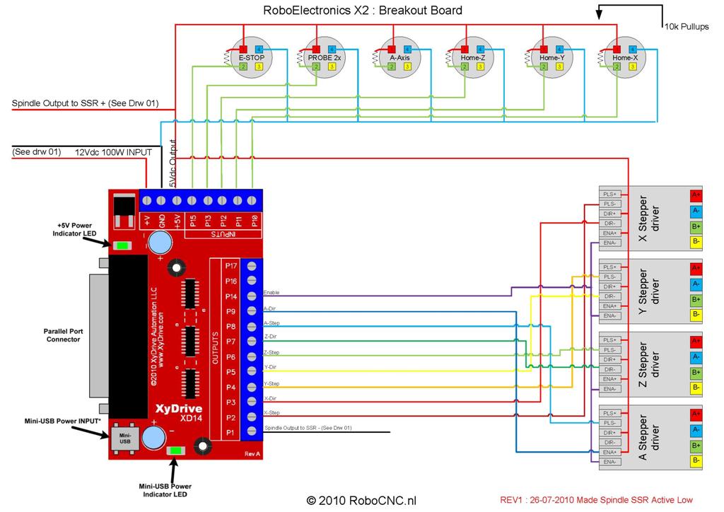
Drawing 3 is the signal part… breakout board and switches..
On the left we see the BOB (Breakout Board part1).
The BOB has 2 power inputs, the 12V marked with +V and GND for the ground,
And the PC side is powered by a mini USB cable (5V logic power).
All the in/outputs on the board are marked with Pxx this represents the pin number of the LPT cable.
P01 is a output that goes to drw1 to switch the SSR on (spindle goes on Zoommm)
Stepper motors turn step by step as the name would apply.
Each step from a motor starts with a pulse from the computer software.
For the outputs I have chosen P2, P4, P6 and P8 for respectively axis X, Y, Z and A.
The pulse signal needs to be connected to the driver on the terminal marked PUL-.
But now the motor driver knows to STEP the motor, but what direction does it need to step?
Well the thought of that one, lucky me… The made a DIR- terminal on the driver for the DIRection.
Again X, Y, Z, A are connected to P3, P5, P7, P9 (it starts to sound simple or not?)
The last signal the drivers need is the ENAble signal (ENA-), this will enable the driver.
If for example the Emergency stop is pressed, ENA will fall away, and the drivers will ignore every pulse.
On every driver there is also a PUL+, DIR+ and a ENA+.
These signals need a constant 5Vdc voltage, which you can get from the BOB marked +5V.
That’s it for the BOB outputs, now we’ll go to the inputs…
On a CNC machine you can use Home and limit switches.
This tells the machine that the machine reached its mechanical maximum, and pulses need to be stopped.
In Mach3 you can choose to do so, although a cheaper and faster way is to use only HOME switches.
On the most negative side of the axis you place a ‘home-switch’ and tell the software the machine limit.
The software now knows the ‘home’ position, and knows how far it can go, so it save you 3 switches.
The connectors used for the switches / sensors are CB radio microphone plugs.
The plugs are 4 pole, although I will only use 3.
Pole 1 is the 5V signal from the BOB and pole 4 is the common GND.
Pole 2 is connected to the BOB input channels, and has a 10kohm resistor from the 5V pole.
This resistor is called a Pull-up resistor (Google is your friend)
If you use normal switches for the home-switches you need to connect the between 2 and 4.
Later on I will make a new post on how to use inductive switches instead.
The 3 axis X, Y and Z all have their own home-switch connector to P10, P11 and P12.
The A axis also has a connector, but I do not use this at this time yet.
On the left you see a connector for the Emergency Stop button (P15) THIS IS NOT OPTIONAL.
The software can work without one, but please DO use one, it can save your life!
If this button / switch is pressed everything will stop moving, including the spindle itself.
The last one is the PROBE (P13), I have this connector two times (parallel).
One in the back-panel for my Z-touch plate (later on), and one in the front for my touch probe (different post).
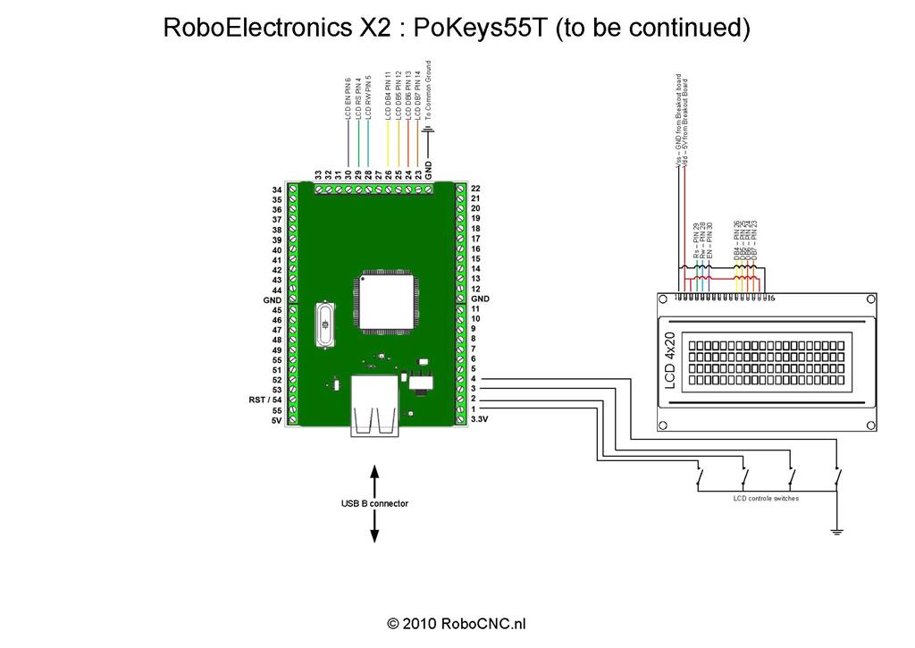
The last drawing (number 4) is about the PoKeys55T.
This is still in the development stage and will get some posts later on.
This is optional to get 55 extra in/outputs from the computer to the controller.
It could be used for LED’s, switches, LCD displays, Pendants Spindle speed control etc.
In my case it will be used for a pendant later on, and for now I connected a 4 row 20 character LCD,
and 4 switches to serve as function keys for the info on the LCD display.
But as I said before this will be discussed in a later post.
The CNC controller is done, and is ready for some test drives.
In the next post I will go setup mach3 to function with this controller.


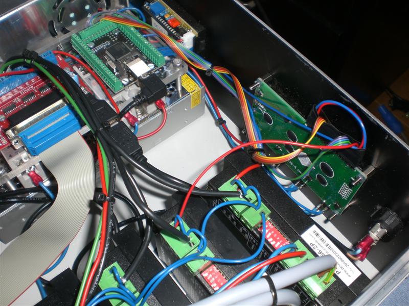
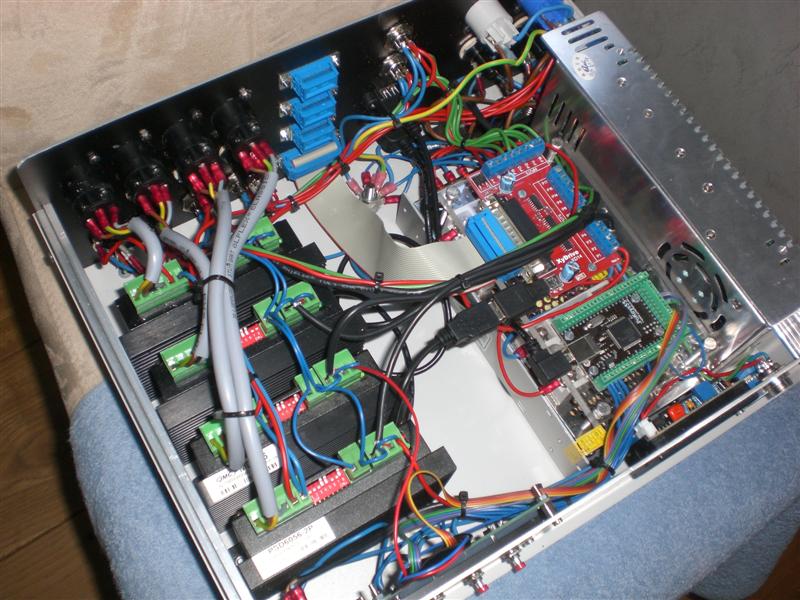
The result….. (Ps. The DB15 connectors are for future auxiliary in combination with the PoKeys)


Next part will be the setting up Mach3
November 2010 Update:
The BOB as mentioned above gave me some problems.
The biggest problem was that it does not have a chargepump,
Therefore the computer could turn on the spindle, when mach3 was not running.
The second problem was the fact that it had some glitches sometimes.
This was because I used the negative outputs from the BOB to drive the drivers…
This update consist of a BOB changeover to a BOB ‘with’ charge-pump, and some rewiring.
The PDF is therefore updated to a version 2, and a new page is added with the new BOB.
 © 2012-2024 RoboCNC.nl | RoboCNC.be | RoboCNC.eu - All Rights Reserved.
Absolutely gorgeous! You rival some of the “professional” products out there. Probably could market this as your own kit build…you might be surprised how many people would buy it due to the fact everything is there. Also I will fire up my Corel Draw and Illustrator skills and see what I can come up with.
Haha thanks Ben, ya well for a complete kit it would become a expensive controller i think..
But there is allready been a upgrade… i’ll post it soon…
Hello,
I am about to graduate and have enough money for a cnc machine (only the mechanical part, no control, motors nor electronics), it an okuma lathe. I have inspected it and it all the mechanics look great. I was wondering if it is a good idea to buy it (only $1100 dollars, yes that is the correct amount) and then use the info you are sharing and bring it back to life.
I am not very good at electronics so I just wanted some advise, should I buy it? how hard would the electronics become I want to use the toolchanger?
Keep the great work you’re doing, greetings from Mexico,
Thank you very much.
Hi there Brujo,
Its difficult for me to answer the question if you should buy it…
If you know for sure the state of the lathe and the price is good i would say ‘do it’…
The electronics for a lathe and a router are indeed similar, although you would want a index function on the chuck for thread cutting, this is not included in my electronics, ‘but’ it is possible to connect it to the breakout board (just google for index lathe mach3).
A toolchanger is also possible to incorporate, just make sure you have a 4th drive to drive the toolchanger.
But you will have to search for examples on internet, many did it before you so don’t try to invent the wheel.
best regards…. Marcel aka Robo