In the process of upgrading my machine i wanted to upgrade some stepper motors.
But after the Y axis upgrade i ran out of space inside the controller enclosure.
So its a great excuse for a new CNC Controller, with bigger drivers and stuff like that.
I have received a lot of questions about the electronics.
And also there are a lot of people who are afraid to build the controller.
There for i will try to explain the build step by step, if it only helps one of you the effort was worth it..
First of all i needed a new controller enclosure, these universal enclosures aren’t cheap but well…
I found a suiteble one at https://www.rs-online.com/ part number :818-637
The external size is approx l=367mm w=300mm h=134mm.

The CNC Controller is the ’thing’ that connects the PC to the CNC Machine.
The PC in my case will have the control software Mach3 running on it.
This software sends pulses t0 the LPT / Parallel Port (DB25) and receives info back through this same port.
The signals from this port will go to the stepper drivers, and these will drive the stepper motors.
You could just connect the wires from the DB25 to the drivers.
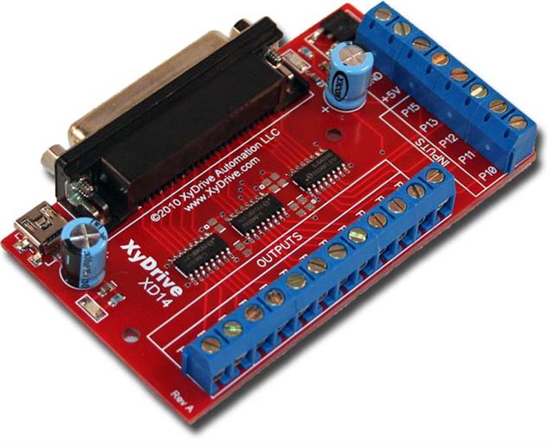
But a better way to do this is to use a BOB (BreakOut board).
A BOB is used to interface the PC to the outside world.
All In/Outputs are terminated in a screw terminal which provides easy wire connections.
On the better breakout boards the incoming side is isolated from the outgoing side.
This is to protect the PC from potentially damaging current and voltage spikes (from the motors).
A lot of these boards are Opto-isolated, but the newer version i use uses radio waves.
The great advantage of this radio wave type is a much higher signal speed (1MHz),
and it operates from a signal as low as 2,7V where most opto boards need 5V.
Is this a advantage? Yes…, because a lot of new PC’s operate with a 3,3V parallel port signal.
The XD14 breakout board : [datasheet]
The signals that come out of the breakout board go to the various features in the controller.
The main thing would be the stepper drivers because the drive the stepper motors.
Mach3 sends an ‘Enable’ signal to enable the motor to turn,
and it sends a STEP and DIR signal to tell the motor to turn 1 STEP in a DIRection.
So this Step en Dir signal need to be translated in actual movement of the stepper motors.
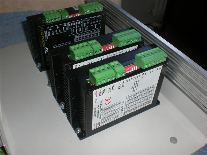
For this we need stepper drivers, and there are a hole lot of those in the market.
So what stepper drivers do you need? wel that depends on the motors you buy.
For example my Y stepper is from a 8-lead type, so i need a 2 phase driver.
The motors are rated 4.2Amp if i connect is in bi-polair parallel (more about the steppers later on).
I want a smooth running machine so i want the drivers to have micro-stepping.
So i need a 2phase microstepping driver with a minimum of 4,2Amp output capability.
On ebay you will find them under names like MD556 and on stappenmotor.nl on MSD-50.5.6.
The microstepping drivers can divide 1 motor revolution in25000 steps if you want to.
This will give very smooth results, although speed of the motor will go down.
These drivers can take up to 50V and drive motors till 5,6Amp [peak].
(Note : As i have collected my parts over time i use 2 different brands)
(On the picture you see 3 drives, but there will be 4 in there eventually)
[MD556 Datasheet] [MSD-50-5.6]

Will the motors turn right now? no they still need some sort of power supply.
In my RoboElectronics X1 controller i used a transformer, ac-dc converter and some big elco’s.
This time i will use a switching power supply to reduce space inside the controller.
The power supply i will be using is a 500W 48V switching power-supply.
The 48V should be ok as its beneath the 50V maximum of the drivers…
The 500W results in a output of max 10,4Amp.
In the next posts you will see that the motors to getter should use more than this.
But although i can not help with the math, this should work fine because :
a: the motors will never ask full maximum current all at the same time.
b: I use micro-stepping (PWM signal) therefor the input should be lower on the drivers.
Since i really wonder what current there will flow i will use a digital panel meter [datasheet].
This part is just a extra and is really not needed to build the controller.
The panel meter uses a shunt resistor to measure the output current of the supply.


Thats it for part 1, to be continued…
 © 2012-2024 RoboCNC.nl | RoboCNC.be | RoboCNC.eu - All Rights Reserved.
Hi, just getting started on my first cnc project, how are the msd drivers working out ? would you recommend them for a first project ? my motors are nema 23;s double stack @4.2A per phase..
Great project, well done.
Billy Graham, Scotland.
Yes i highly recommend them, very smooth driving, great power reduction due to the microstepping.
Works great for me…. And its verily cheap as these drivers all come from China i guess..
Hi,
I have recently built my first cnc machine. Electronics is a dark area for me, so I purchased a complete kit (breakout board, driver boards and 3 nema 23 steppers). The maximum speed I can get on the x&y axis before stalling is 20 inch (500mm)/ min, which is disappointing. My leadscrews are 15 tpi threaded rod. Upon studying the documents that came with the kit, I noticed that in parallel, the motors have a rating of 5amp. But my stepper drivers have a max output of only 3 amps. At 5 amps the motor has a power rating of 13.75 Watts, but at 3 amps can only provide 4.95 Watts, which is only just over 1/3 of the potential power. I pointed this out to my supplier, but he failed to answer my question.
Could Marcel, or anyone else here confirm whether I am correct in my assumption that this is causing my problems?
Thanks, Gareth
Well Gareth lets first of all take this lesson, first think and read all information before purchasing….
I know this sounds teacher like, but please understand that this hobby requires a lot of reading and learning…. (otherwise you would have to buy a machine…)
Nema 23 only tells me something about the model/size of the motor….
Nothing about maximum speed, or holding torque….
If you want to solve the speed problem you will have to start reading about some things that hang together here….. :
– Indeed more TPI’s results in less speed and better accuracy.
– Are u using micro stepping? the more micro steps you use the less speed you will get.
– Does your driver software use the max kernell speed (for example mach3)
– And much more… (sorry)
Well anyway, no one can tell you what to do without ‘all’ the information…
Now the important part… : parallel vs serie
You probably have a 8 wire stepper? and connected id pi-polar series ?
Well connecting it in bi-polar parallel will give it way more torque….
but it will not really effect the maximum speed of the motor….
The maximum speed of the motor can only be improved by providing more ‘voltage’ not ‘current’
Conclusion…… read more my friend…
Im not trying to be te bad guy, but only you can solve it by finding out what you can do with your steppers, and your drivers…
I use 48V although my motors rate about 4V, but the drivers can handle 50…
But this can only be done by microstepping drives for example
Hope it helped a bit
Thanks Marcel,
I don’t think you are a bad guy at all. My wife still lives in Netherlands and so I have neen there many times and all Dutch people I’ve met are very helpful.
I have done a lot of reading, but sadly much of it after buying the kit. I have set all my motors to microstepping at 1/8. They are 8 wire and I have them in parallel (4 pairs of 2 wires). From the description of the motors I have this info;- holding torque =3.1 Nm. Parallel operation 2.5V @ 5A, 0.55 ohm, 3 mH
So it is volts I need. I will look into it. Thanks again for your help
Oke this does change the story a bit…. (you see, its hard as i can not see your connection and parts….)
you connected the motors bi-polar parallel even though the drives can not handle this….
‘IF’ your drives can not deliver 5A you can not connect the motors this way….
You will have to downgrade to bi-polar series, or upgrade the drives….
The 3 posible connections are :
Unipolar:
Don’t even bother to understand this one 😉 (low torque, never good)
Bipolar with series windings:
This gives higher inductance but lower current per winding.
(high torque, but lower speed)
Bipolar with parallel windings:
This requires higher current but can perform better as the winding inductance is reduced.
(High torque and higher speed)
You should think you would now have the best connection because you used the last of this three…
But your drives can not get this to work properly
(and you might burn your drives….)
So please first try the bi-polar series, and see what happens….
Find out what the maximum rated voltage is you can supply the drives with, find a good power supply close to that ‘voltage’ and do another test…
(For maximum speed testing, keep your acceleration down.)
Hi Marcel,
I told you that I am an electrical “dummy”. But I think I was on the right lines when I pointed out to the my supplier that the drivers were only 3 amp rated and the motors had a 5 amp rating. I did try 1 motor in series a few weeks ago. The perfrmance was terrible and the noise unbearable. So I reverted to the parallel configuration. The power supply is rated 36v, but I have no idea how to measure what is being sent to the motors.
Like most of us I don’t have an endless supply of money, so I guess I will have to live with it for a while.
I have been considering upgrading the leadscrews to acme thread. Am I on the right lines to think that I would get more speed with a better quality screw with less TPI? I have been put off by the high cost of lead nuts. I noticed that you have made some from teflon. Is this difficult to do and is there an explanation anywhere on the site?
Your site is a great source of information and inspiration. I have already started redisigning my z axis after watching your video here.
Thanks again,
Gareth
Gareth,
You say you have to live with this…. But again i tell you that you will probably blow your drives if you keep the motors parallel.
When you say the motors turned terrible i have the idea your connection was not the way it should be…..
Let the supplier tell you ‘how to’ connect the motors to the drives to be sure…. all of the 8 wires have only 1 proper place to be connected…
For example you could have connected 1 coil the wrong way around, this way one of the coils tries to turn the motor the other way…. (simplified)
If you have the datasheets of the motor AND the drives you can also email me, but i think this comment section is not the best place to go further on this subject….
You ask me if acme thread is a better solution, but don’t tell me what you have now 🙂
Well the best thing is a ball-screw type… this ‘uses’ way less torque…. But is the most expensive one…
The acme thread is the next best, but they are far from close to each other….
But well all this information is written on different pages on this website, so place read all about that first…
The teflon nuts are made on my lathe, and is impossible without one.. (and after a year they needed replacement….)
Less TPI means a faster machine indeed, but step resolution goes down…
For example i have 5mm pitch, witch is about 5tpi (5 x 5mm is about 1 inch).
If your motor could turn 100rpm you could move the machine : 100 / 5tpi = 20 inch/min (or : 5mm pitch x 100 rpm = 500mm / min)
If you would have 10 tpi you would have to run 2 minutes for the same distance….
But….
You have 1/8 micro stepping, normal rotation of a stepper is 200 steps per revolution….
So now you do 200 x 8 = 1600 steps per rev.
The smallest your software can do is 1 step, so… :
With 5mm pitch : 1 step = 1/1600 of a rev = 5mm / 1600 = 0.003125 mm
With 10mm pitch : its double 0.00625 (btw this would still be great i think… but its just to show you)
If you still have ‘on topic’ questions feel free to comment, if it becomes a greater discussion on ‘your’ machine, please email me…
And thanks for the nice words…. 😉
Hi Marcel,
This question is about power supplies. I have read the section on this page, I have 3 motors requiring 5A each. I want to put 70V through them. I understand what you say about them not all wanting maximum current at the same time. So what size power supply would I need? By my calculation :
500W @ 70V = 7.14A
750W @ 70V = 10.7A
Most of the cnc suppliers I have looked at are offering as a maximum 500W power supplies and say it is capable of driving 3 steppers, or more. 7A seems a a bit on the low side to me. (but what do I know)
I have also noticed that some are selling unregulated power supplies. Can these cause problems?
Sorry for so manyy questions, but I am sure I’m not alone in this power supply quandry.
Best regards,
Gareth
Gareth,
Your calculation on the power supply’s is correct, that is indeed the maximum current the power supply’s can deliver.
The calculation upon the steppers is not that easy, as they are using a micro stepping technology.
Can it be calculated? Yes.. of course… But can I do this? Nope… and no one i know…
When the shops sell them that way, you can be leave them…
On my RoboCNC X1 Router, i have a current display, and a big power supply….
But i have never seen the display go over 3,5Amps… And thats with 4 drives/stepper simultaneous.
For my new setup i will use the Leadshine SPS705 power supply (5 amps cont. and 7 Amps peak).
This will be used to drive 4 drives, Leadshine DM856 (5,6 Amps each (Peak)).
This is not yet tested out, but i really believe this will be way more then enough to drive all 4 drivers to the maximum current.
Sorry i really dont know how to use math to help you out, and if anyone knows? Please comment.
But i do know, that you do not have to use such a big supply to drive the micro stepping drives.
Thanks Marcel. I’ve seen enough of your videos to see how fast your machine runs and if that is only drawing 3.5A, That is a reassurance. The SPS705 has been suggested to me by Impulse, so I will go with that 1.
I have posted the same question on CNC.com . If I get any info there I will post it here I wiill post it here for others.
Best regards,
Gareth